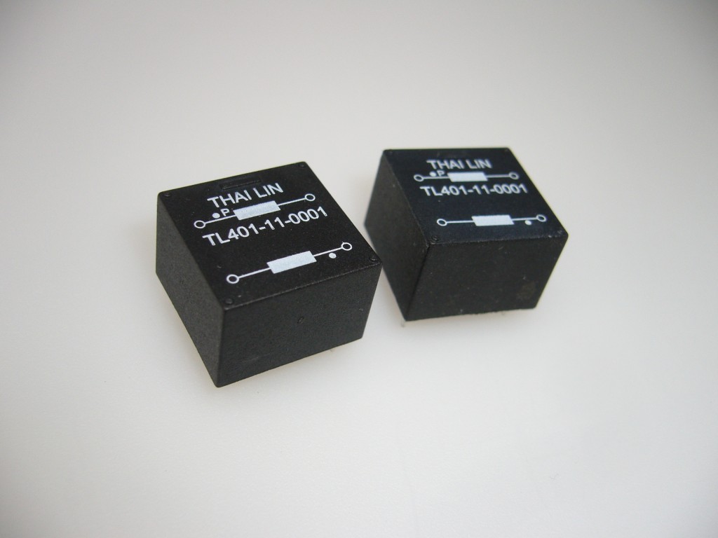
Pulse Transformer (TL401 Series) |
[][] | Features:
] |
|
| [ |
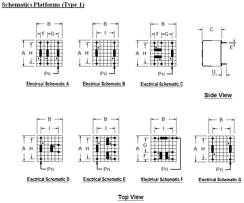
| Product Series | Dimension (mm) | Electrical Schematic | Weight (g) | ||||||||
| A | B | C | D | E | F | G | H | I | |||
| TL401-13 | 18.6 | 18.3 | 14.0 | 4.0 | SQ0.5 | 5.0 | 7.5 | 15.0 | 12.5 | A,B,C | 9.5 |
| TL401-11 | 18.6 | 18.3 | 14.0 | 4.0 | SQ0.5 | 5.0 | 10.0 | 15.0 | 12.5 | D,E,F,G | 9.0 |
| Tolerance (mm) | max. | max. | max. | min. | ± 0.1 | ± 0.2 | ± 0.3 | ± 0.5 | ± 0.5 | — | approx. |
Note: Unused pins are omitted for standard parts.
Part Number Designation:
TL401-RW-XYZZ
Where R = Core size
(1) EF16 (2) EF20 (3) EF25 (4) EF30
W = No. of bobbin section
(1) Single (2) Double (3) Three
X = No. of winding
Y = Electrical schematic
ZZ = Winding Part no.
| Part Number | Turn Ratio ±2% | Ref. Pri L (mH) | Ref. Pri ET (Vus) | Max. Leakage L (uH) | Ref. Inter Cap (pF) | Max. Pri DCR (ohm) | Max. Sec 1 DCR (ohm) | Max. Sec 2 DCR (ohm) | Dielectric Strength (Vrms) | Electrical Schematic |
| TL401-13-3A01
TL401-13-3A02 TL401-13-3A03 TL401-13-3A04 TL401-13-3A05 TL401-13-3A06 TL401-13-3A07 TL401-13-3A08 TL401-13-3A09 TL401-13-3A10 |
1 : 1 : 1
1 : 1 : 1 3 : 1 : 1 1 : 1 : 1 3 : 1 : 1 2 : 1 : 1 1 : 1 : 1 1 : 1 : 1 1 : 1 : 1 2 : 1 : 1 |
2.5
1.5 16.5 2.5 15.0 17.0 1.1 0.5 1.60 18.2 |
250
200 400 250 400 410 170 120 130 440 |
90
55 50 85 70 140 45 20 60 135 |
10
8 10 7 9 9 6 7 5 8 |
0.6
0.4 2.3 0.8 2.8 3.1 0.55 0.3 0.5 4.6 |
0.6
0.4 0.5 0.8 0.9 1.5 0.55 0.3 0.5 0.86 |
0.6
0.4 0.5 0.8 0.9 1.5 0.55 0.3 0.5 0.86 |
4000
4000 4000 4000 4000 4000 4000 4000 4000 4000 |
A
A A A A A A A A A |
| TL401-13-2B01
TL401-13-2B02 TL401-13-2B03 TL401-13-2B04 TL401-13-2B05 TL401-13-2B06 TL401-13-2B07 TL401-13-2B08 TL401-13-2B09 TL401-13-2B10 TL401-13-2B11 |
1 : 1
2 : 1 2 : 1 3 : 1 1 : 1 1 : 1 1 : 1 1 : 1 2 : 1 2 : 1 3 : 1 |
2.2
7 17 12 8 2.5 8 8 8 19 21 |
250
430 410 340 500 250 450 460 300 440 450 |
40
35 80 30 150 40 100 100 40 85 35 |
8
7 9 8 10 8 10 10 10 8 8 |
0.8
2.1 3.2 2 1.2 0.6 1.48 1.8 1.5 5.5 5 |
0.8
1.1 1.6 0.8 1.2 0.6 1.48 1.2 0.8 0.9 0.7 |
—
— — — — — — — — — — |
4000
4000 4000 4000 4000 4000 4000 4000 4000 4000 4000 |
B
B B B B B B B B B B |
| TL401-13-3C01
TL401-13-3C02 TL401-13-3C03 |
1 : 1 : 1
1 : 1 : 1 3 : 1 : 1 |
2.5
3.45 19 |
250
280 450 |
75
72 70 |
7
9 8 |
0.75
0.65 5 |
0.75
0.65 0.7 |
0.75
0.65 0.7 |
4000
4000 4000 |
C
C C |
| TL401-11-2D01
TL401-11-2D02 TL401-11-2D03 |
1 : 1.3
1 : 1 1 : 1 |
0.20
1.70 1.40 |
72
200 180 |
1.2
5 3 |
11
25 20 |
0.12
0.32 0.3 |
0.18
0.26 0.32 |
—
— — |
5000
3750 4000 |
D
D D |
| TL401-11-3E01
TL401-11-3E02 |
1 : 1.3 : 1.3
1 : 1 : 1 |
0.2
2.50 |
72
260 |
1.2
5 |
12
25 |
0.2
0.5 |
0.3
0.65 |
0.3
0.65 |
5000
3200 |
E
E |
| TL401-11-3F01
TL401-11-3F02 TL401-11-3F03 TL401-11-3F04 TL401-11-3F05 TL401-11-3F06 |
1 : 1 : 1
1 .13 : 1 : 1 1.4 : 1 : 1 1 : 1.2 : 1.2 1 : 1 : 1 1 : 1 : 1 |
0.82
1.88 2.10 1.20 1.8 0.32 |
150
220 230 180 220 90 |
2
4 4 3 2.5 0.8 |
22
20 20 22 23 20 |
0.25
0.52 0.55 0.43 0.415 0.07 |
0.35
0.45 0.4 0.4 0.35 0.12 |
0.45
0.45 0.4 0.6 0.48 0.16 |
4200
4000 4000 4000 3100 4400 |
F
F F F F F |
| TL401-11-2G01
TL401-11-2G02 TL401-11-2G03 TL401-11-2G04 |
1 : 1
1 : 1 2 : 1 3 : 1 |
2.5
2.5 2.5 5 |
250
260 260 360 |
3
3 4 5 |
80
60 50 40 |
0.62
0.7 1.0 1.2 |
0.75
0.7 0.3 0.3 |
—
— — — |
3200
3200 3200 3200 |
G
G G G |
Note: (1) Primary Inductance measured at 10 kHz, 0.05V. (Sec coils open)
(2) Leakage Inductance measured at the secondary side, short circuit at the primary side.
If there are several secondary coils only one side at the time is connected.
(3) High potential tested for all isolation windings.
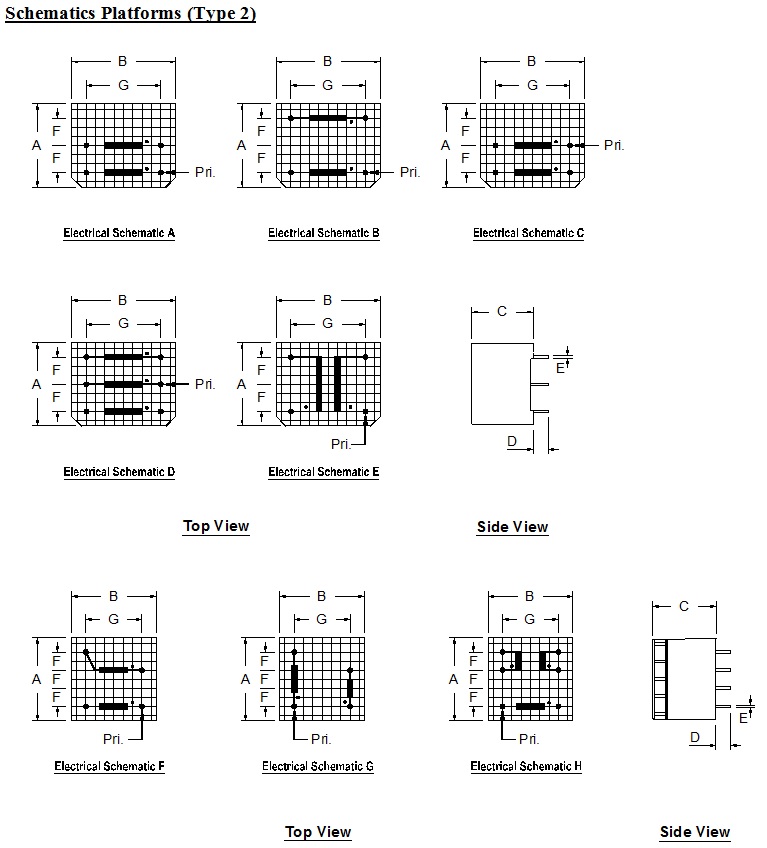
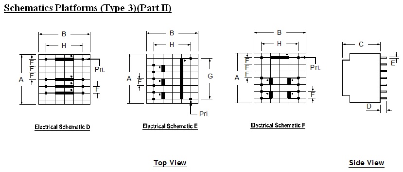
| Product Series | Dimension (mm) | Electrical Schematic | Weight (g) | ||||||
| A | B | C | D | E | F | G | |||
| TL401-13 | 23.0 | 28.0 | 17.0 | 4.0 | SQ0.64 | 7.5 | 20.0 | A,B,C,D,E | 20 |
| TL401-11 | 22.8 | 22.8 | 17.5 | 4.0 | SQ0.64 | 5.0 | 15.0 | F,G,H | 17 |
| Tolerance (mm) | max. | max. | max. | min. | ± 0.1 | ± 0.2 | ± 0.3 | — | approx. |
Note: Unused pins are omitted for standard parts.
| Part Number | Turn Ratio ±2% | Ref. Pri L (mH) | Ref. Pri ET (Vus) | Max. Leakage L (uH) | Ref. Inter Cap (pF) | Max. Pri DCR (ohm) | Max. Sec 1 DCR (ohm) | Max. Sec 2 DCR (ohm) | Dielectric Strength (Vrms) | Electrical Schematic |
| TL401-23-2A01
TL401-23-2A02 |
1 : 1
1 : 1 |
7.70
2.10 |
650
300 |
85
30 |
7
6 |
1.15
0.55 |
1.15
0.55 |
—
— |
4000
4000 |
A
A |
| TL401-23-2B01 | 1 : 1 | 2.90 | 370 | 80 | 5 | 0.6 | 0.6 | — | 4000 | B |
| TL401-23-2C01
TL401-23-2C02 TL401-23-2C03 |
1 : 1
1 : 1 1 : 1 |
5.0
3.0 28.0 |
500
380 1100 |
85
55 56 |
6
8 30 |
1.2
0.6 1.9 |
1.2
0.6 2.2 |
—
— — |
4000
4000 2500 |
C
C C |
| TL401-23-3D01
TL401-23-3D02 TL401-23-3D03 TL401-23-3D04 TL401-23-3D05 |
3 : 1 : 1
1 : 1 : 1 1 : 1 : 1 3 : 1 : 1 1 : 1 : 1 |
121
8 2.0 15.0 3 |
1550
600 300 520 380 |
270
230 80 70 90 |
10
8 7 8 9 |
17
1.5 0.55 2 0.6 |
3.5
1.5 0.55 0.55 0.6 |
3.5
1.5 0.55 0.55 0.6 |
4000
4000 4000 4000 4000 |
D
D D D D |
| TL401-23-2E01 | 1 : 1 | 3 | 380 | 5 | 80 | 0.9 | 0.9 | — | 6000 | E |
| TL401-21-2F01
TL401-21-2F02 TL401-21-2F03 TL401-21-2F04 |
1 : 1
2 : 1 3 : 1 1 : 1 |
3.8
5.2 4.7 0.31 |
420
500 480 130 |
7
9 9 0.9 |
35
26 25 20 |
0.45
0.5 0.45 0.1 |
0.5
0.25 0.15 0.1 |
—
— — — |
4000
4000 4000 4000 |
F
F F F |
| TL401-21-2G01 | 3 : 1 | 1.68 | 280 | 6 | 22 | 0.155 | 0.066 | — | 3200 | G |
| TL401-21-3H01
TL401-21-3H02 TL401-21-3H03 |
1 : 1 : 1
2 : 1 : 1 1 : 1 : 1 |
3.5
5.1 0.36 |
420
500 130 |
6
8 0.6 |
39
31 23 |
0.8
0.55 0.09 |
0.8
0.2 0.1 |
0.8
0.25 0.1 |
4000
4000 4000 |
H
H H |
Note: (1) Primary Inductance measured at 10 kHz, 0.05V. (Sec coils open)
(2) Leakage Inductance measured at the secondary side, short circuit at the primary side.
If there are several secondary coils only one side at the time is connected.
(3) High potential tested for all isolation windings.
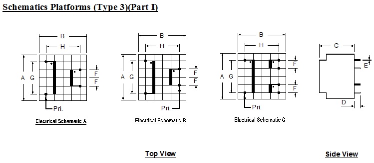
| Product Series | Dimension (mm) | Weight (g) | |||||||
| A | B | C | D | E | F | G | H | ||
| TL401-31(I) | 28.0 | 28.0 | 21.0 | 4.0 | SQ0.64 | 5.0 | 20.0 | 20.0 | 40 |
| Tolerance (mm) | max. | max. | max. | min. | ± 0.1 | ± 0.2 | ± 0.3 | ± 0.5 | approx. |
Note: Unused pins are omitted for standard parts.
| Part Number | Turn Ratio ±2% | Ref. Pri L (mH) | Ref. Pri ET (Vus) | Max. Leakage L (uH) | Ref. Inter Cap (pF) | Max. Pri DCR (ohm) | Max. Sec 1 DCR (ohm) | Max. Sec 2 DCR (ohm) | Dielectric Strength (Vrms) | Electrical Schematic |
| TL401-31-2A01
TL401-31-2A02 TL401-31-2A03 TL401-31-2A04 TL401-31-2A05 TL401-31-2A06 |
1 : 1
1 : 1 2 : 1 2 : 1 4 : 1 1.5 : 1 |
2.2
12.3 7.0 80.0 140 95 |
500
1100 2500 7600 8800 10500 |
5
12 90 950 1100 1600 |
38
50 45 65 45 53 |
0.4
0.7 1.0 6.0 12.3 13.5 |
0.4
0.8 0.5 1.9 1.3 7.1 |
—
— — — — — |
4000
4000 4000 4000 4000 4000 |
A
A A A A A |
| TL401-31-2B01 | 3 : 1 | 9.7 | 1000 | 12 | 31 | 0.6 | 0.2 | — | 4000 | B |
| TL401-31-3C01
TL401-31-3C02 TL401-31-3C03 TL401-31-3C04 |
1 : 1 : 1
2 : 1 : 1 1 : 1 : 1 3 : 1 : 1 |
2.45
12.6 12.8 5.1 |
500
1100 1100 1120 |
2.5
14.5 14.5 16.5 |
35
40 50 32 |
0.4
0.9 0.85 0.6 |
0.4
0.4 0.85 0.2 |
0.4
0.4 0.85 0.2 |
4000
4000 4000 4000 |
C
C C C |
Note: (1) Primary Inductance measured at 10 kHz, 0.05V. (Sec coils open)
(2) Leakage Inductance measured at the secondary side, short circuit at the primary side.
If there are several secondary coils only one side at the time is connected.
(3) High potential tested for all isolation windings.
| Product Series | Dimension (mm) | Weight (g) | |||||||
| A | B | C | D | E | F | G | H | ||
| TL401-31(II) | 28.0 | 28.0 | 21.0 | 4.0 | SQ.0.64 | 3.81 | 22.86 | 20.0 | 40 |
| Tolerance | max. | max. | max. | min. | ± 0.1 | ± 0.2 | ± 0.3 | ± 0.5 | approx. |
Note: Unused pins are omitted for standard parts.
| Part Number | Turn Ratio ±2% | Ref. Pri L (mH) | Ref. Pri ET (Vus) | Max. Leakage L (uH) | Ref. Inter Cap (pF) | Max. Pri DCR (ohm) | Max. Sec 1 & 2 DCR (ohm) | Max. Sec 3 & 4 DCR (ohm) | Electrical Schematic |
| TL401-31-4D01
TL401-31-4D02 TL401-31-4D03 TL401-31-4D04 |
1 : 1 : 1 : 1
1 : 1.2 : 1.2 : 1.2 2 : 1 : 1 : 1 3 : 1 : 1 : 1 |
3.6
3.6 14.4 19.4 |
720
720 1440 1672 |
2.8
2.5 18.5 18.9 |
29
31 30 24 |
0.20
0.22 0.45 0.52 |
1.5
1.8 1.6 1.3 |
1.5
1.8 1.6 1.3 |
D
D D D |
| TL401-31-4E01
TL401-31-4E02 |
2 : 1 : 1 : 1
3 : 1 : 1 : 1 |
14.4
19.4 |
1440
1672 |
11.0
20.0 |
33
22 |
0.45
0.52 |
1.7
1.3 |
1.7
1.3 |
E
E |
| TL401-31-5F01
TL401-31-5F02 TL401-31-5F03 TL401-31-5F04 |
1 : 1 : 1 : 1 : 1
1 : 1.2 : 1.2 : 1.2 : 1.2 2 : 1 : 1 : 1 : 1 3 : 1 : 1 : 1 : 1 |
3.6
3.6 14.4 19.4 |
720
720 1440 1672 |
1.9
1.8 9.5 15.0 |
65
63 60 46 |
0.25
0.25 0.5 0.57 |
1.4
1.7 1.4 1.1 |
1.7
2.0 1.8 1.5 |
F
F F F |
Note: (1) Primary Inductance measured at 10 kHz, 0.05V. (Sec coils open)
(2) Leakage Inductance measured at the secondary side, short circuit at the primary side.
If there are several secondary coils only one side at the time is connected.
(3) High potential tested for all isolation windings.
| Product Catalog | |